
All of the visual types in SciChart inherit from the type BaseSceneEntity. This is a class which represents an entity on the screen in the 3D world.
It is possible to create entities which inherit BaseSceneEntity and add them to the SciChart3DSurface. For example, if you want to add some simple geometry to the 3D Chart, you can do it with this API.
Basics of the SceneEntity API
In the example Add Geometry to a 3D Scene we demonstrate a simple CubeGeometry class which draws a cube with wireframe outline. The code for CubeGeometry is included below for example purposes.
| CubeGeometry.cs |
Copy Code |
|---|---|
/// <summary> /// A class to demonstrate a 3D Geometry added to the SciChart3D Scene. Created using our BaseSceneEntity and Mesh APIs /// </summary> public class CubeGeometry : BaseSceneEntity { private readonly Vector3 bottomRight; private readonly Vector3 topLeft; private readonly Color cubeColor; public CubeGeometry(Vector3 topLeft, Vector3 bottomRight, Color cubeColor) { // Shady : Setting the position of scene entities will be used back when sorting them from camera perspective back to front using (TSRVector3 centerPosition = new TSRVector3( 0.5f*(topLeft.x + bottomRight.x), 0.5f*(topLeft.y + bottomRight.y), 0.5f*(topLeft.z + bottomRight.z))) { SetPosition(centerPosition); } this.topLeft = topLeft; this.bottomRight = bottomRight; this.cubeColor = cubeColor; } /// <summary> /// Determines a kind of the entity. If SCRT_SCENE_ENTITY_KIND_TRANSPARENT then the 3D Engine must make some internal adjustments to allow order independent transparency /// </summary> public override eSCRTSceneEntityKind GetKind() { return cubeColor.A == 255 ? eSCRTSceneEntityKind.SCRT_SCENE_ENTITY_KIND_OPAQUE : eSCRTSceneEntityKind.SCRT_SCENE_ENTITY_KIND_TRANSPARENT; } /// <summary> /// Called when the 3D Engine wishes to update the geometry in this element. This is where we need to cache geometry /// before draw. /// </summary> /// <param name="e">The <see cref="IRenderPassInfo3D" /> containing parameters for the current render pass.</param> public override void UpdateScene(IRenderPassInfo3D e) { } /// <summary> /// Called when the 3D Engine wishes to render this element. This is where geometry must be drawn to the 3D scene /// </summary> /// <param name="e">The <see cref="IRenderPassInfo3D" /> containing parameters for the current render pass.</param> public override void RenderScene(IRenderPassInfo3D e) { // y 1--------0 // | /| /| // | 5--------4 | // | | | | | // | | | | | // | | 2--------3 // | z | / |/ // | / 6--------7 // |/ // ----------- X Vector3[] corners = { new Vector3(topLeft.X, topLeft.Y, topLeft.Z), //0 new Vector3(bottomRight.X, topLeft.Y, topLeft.Z), //1 new Vector3(bottomRight.X, bottomRight.Y, topLeft.Z), //2 new Vector3(topLeft.X, bottomRight.Y, topLeft.Z), //3 new Vector3(topLeft.X, topLeft.Y, bottomRight.Z), //4 new Vector3(bottomRight.X, topLeft.Y, bottomRight.Z), //5 new Vector3(bottomRight.X, bottomRight.Y, bottomRight.Z), //6 new Vector3(topLeft.X, bottomRight.Y, bottomRight.Z), //7 }; Vector3[] normals = { new Vector3(+0.0f, +0.0f, -1.0f), //front new Vector3(+0.0f, +0.0f, +1.0f), //back new Vector3(+1.0f, +0.0f, +0.0f), //right new Vector3(-1.0f, +0.0f, +0.0f), //left new Vector3(+0.0f, +1.0f, +0.0f), //top new Vector3(+0.0f, -1.0f, +0.0f), //bottom }; // We create a mesh context. There are various mesh render modes. The simplest is Triangles // For this mode we have to draw a single triangle (three vertices) for each corner of the cube // You can see using (var meshContext = base.BeginLitMesh(TSRRenderMode.TRIANGLES)) { // Set the Rasterizer State for this entity SCRTImmediateDraw.PushRasterizerState(RasterizerStates.CullBackFacesState.TSRRasterizerState); // Set the color before drawing vertices meshContext.SetVertexColor(cubeColor); // Now draw the triangles. Each face of the cube is made up of two triangles // Front face SetNormal(meshContext, normals[0]); SetVertex(meshContext, corners[0]); SetVertex(meshContext, corners[2]); SetVertex(meshContext, corners[1]); SetVertex(meshContext, corners[2]); SetVertex(meshContext, corners[0]); SetVertex(meshContext, corners[3]); // Right side face SetNormal(meshContext, normals[2]); SetVertex(meshContext, corners[1]); SetVertex(meshContext, corners[2]); SetVertex(meshContext, corners[6]); SetVertex(meshContext, corners[1]); SetVertex(meshContext, corners[6]); SetVertex(meshContext, corners[5]); // Top face SetNormal(meshContext, normals[4]); SetVertex(meshContext, corners[2]); SetVertex(meshContext, corners[7]); SetVertex(meshContext, corners[6]); SetVertex(meshContext, corners[7]); SetVertex(meshContext, corners[2]); SetVertex(meshContext, corners[3]); // Left side face SetNormal(meshContext, normals[3]); SetVertex(meshContext, corners[3]); SetVertex(meshContext, corners[0]); SetVertex(meshContext, corners[4]); SetVertex(meshContext, corners[3]); SetVertex(meshContext, corners[4]); SetVertex(meshContext, corners[7]); // Back face SetNormal(meshContext, normals[1]); SetVertex(meshContext, corners[7]); SetVertex(meshContext, corners[5]); SetVertex(meshContext, corners[6]); SetVertex(meshContext, corners[7]); SetVertex(meshContext, corners[4]); SetVertex(meshContext, corners[5]); // Bottom face SetNormal(meshContext, normals[5]); SetVertex(meshContext, corners[0]); SetVertex(meshContext, corners[1]); SetVertex(meshContext, corners[5]); SetVertex(meshContext, corners[0]); SetVertex(meshContext, corners[5]); SetVertex(meshContext, corners[4]); } // Revert raster state SCRTImmediateDraw.PopRasterizerState(); // Set the Rasterizer State for wireframe SCRTImmediateDraw.PushRasterizerState(RasterizerStates.WireframeState.TSRRasterizerState); // Create a Line Context for a continuous line and draw the outline of the cube var lineColor = Color.FromArgb(0xFF, cubeColor.R, cubeColor.G, cubeColor.B); CreateSquare(2.0f, true, lineColor, new[] { corners[0], corners[1], corners[2], corners[3] }); CreateSquare(2.0f, true, lineColor, new[] { corners[4], corners[5], corners[6], corners[7] }); CreateSquare(2.0f, true, lineColor, new[] { corners[0], corners[4], corners[7], corners[3] }); CreateSquare(2.0f, true, lineColor, new[] { corners[5], corners[1], corners[2], corners[6] }); // Revert raster state SCRTImmediateDraw.PopRasterizerState(); } private void CreateSquare(float lineThickness, bool isAntiAlias, Color lineColor, Vector3[] vertices) { using (var lineContext = base.BeginLineStrips(lineThickness, isAntiAlias)) { lineContext.SetVertexColor(lineColor); foreach (var v in vertices) { SetVertex(lineContext, v); } SetVertex(lineContext, vertices.First()); lineContext.Freeze(); lineContext.Draw(); } } private void SetVertex(IImmediateLitMeshContext meshContext, Vector3 vector3) { meshContext.SetVertex3(vector3.X, vector3.Y, vector3.Z); } private void SetVertex(ILinesMesh linesContext, Vector3 vector3) { linesContext.SetVertex3(vector3.X, vector3.Y, vector3.Z); } private void SetNormal(IImmediateLitMeshContext meshContext, Vector3 vector3) { meshContext.Normal3(vector3.X, vector3.Y, vector3.Z); } /// <summary> /// Performs selection on this entity, setting the IsSelected flag to True or False on the specified /// <see cref="VertexId">Vertex Ids</see> /// </summary> /// <param name="isSelected">if set to <c>true</c> the vertices become .</param> /// <param name="vertexIds">The vertex ids.</param> public override void PerformSelection(bool isSelected, List<VertexId> vertexIds) { // Do nothing } } | |
When placed on a chart this becomes a re-usable 3D object, as demonstrated in the Add Geometry to a 3D Scene example:
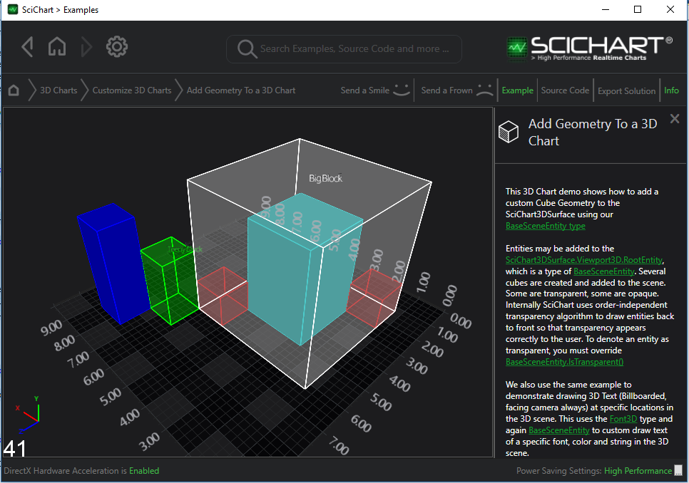
Adding BaseSceneEntity Types to the SciChart3DSurface
The CubeGeometry objects are added to the SciChart3DSurface.Viewport3D.RootEntity which contains a scene graph of the entire 3D scene. Have a look at the code below:
| Adding BaseSceneEntities to the Chart |
Copy Code |
|---|---|
var cubeA = new CubeGeometry(new Vector3(0.0f, 0.0f, 0.0f), new Vector3(50.0f, 50.0f, 50.0f), Color.FromArgb(128, 255,0,0)); var cubeB = new CubeGeometry(new Vector3(50.0f, 0.0f, 50.0f), new Vector3(100.0f, 100.0f, 100.0f), Color.FromArgb(128, 0, 255, 0)); var cubeC = new CubeGeometry(new Vector3(100.0f, 0.0f, 100.0f), new Vector3(150.0f, 150.0f, 150.0f), Color.FromArgb(255, 0, 0, 255)); var cubeD = new CubeGeometry(new Vector3(-100.0f, 0.0f, -100.0f), new Vector3(0.0f, 150.0f, 0.0f), Color.FromArgb(255, 0, 255, 255)); var cubeE = new CubeGeometry(new Vector3(-150.0f, 0.0f, -150.0f), new Vector3(50.0f, 200.0f, 50.0f), Color.FromArgb(128, 255, 255, 255)); // force a far position on this cube ( user can do this in cases where a box inside another ) var cubeF = new CubeGeometry(new Vector3(-150.0f, 0.0f, -150.0f), new Vector3(-100.0f, 50.0f, -100.0f), Color.FromArgb(128, 255, 0, 0)); TSRVector3 farPosition = new TSRVector3(20000.0f, 20000.0f, 2000.0f); cubeF.SetPosition(farPosition); // Add the cubes to the 3D Scene sciChart3DSurface.Viewport3D.RootEntity.Children.Add(cubeA); sciChart3DSurface.Viewport3D.RootEntity.Children.Add(cubeB); sciChart3DSurface.Viewport3D.RootEntity.Children.Add(cubeC); sciChart3DSurface.Viewport3D.RootEntity.Children.Add(cubeD); sciChart3DSurface.Viewport3D.RootEntity.Children.Add(cubeE); sciChart3DSurface.Viewport3D.RootEntity.Children.Add(cubeF); | |
Our 3D Cubes are added at various positions defined by Vector3 structs. It should be noted that the coordinates are in World Coordinates. Conversion between World and Data Coordinates is performed by the axis, and discussed here.
What can the BaseSceneEntity API do?
Functions exposed to the user include:
- Drawing vertices, normals and geometry to draw lines, simple shapes in 3D space
- Draw text on the chart at specific X,Y,Z locations
It is also theoretically possible to create custom 3D Chart types, however we haven't exposed enough of the API yet to allow is. If you do have a custom requirement, then contact us as we would love to hear it.