The Software War Behind Formula 1 That Nobody Talks About
When people think about what wins a Formula 1 championship, they think about aerodynamics. Engine power. Tyre strategy. The driver. […]

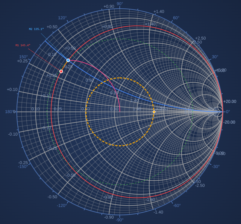
SciChart.js is best known for high-performance standard chart types, including line charts, scatter plots, heatmaps, and financial candlesticks. But underneath those chart types is a deeply extensible rendering pipeline that most developers never touch. This post explores that pipeline by building a fully interactive Smith chart from scratch, using only the standard SciChart.js API.
A Smith chart is a graphical tool RF and microwave engineers have used since 1939 to solve impedance matching problems. At radio frequencies, mismatched impedances between source and load cause signal reflections that waste power and can damage equipment. The Smith chart makes this tractable by mapping complex impedance onto the unit disk through a Möbius transform — turning an algebraic problem into a geometry problem.
The chart’s grid is made of two families of curves:
Adding each type of circuit component moves the operating point along a predictable arc. The goal of a perfect impedance match is always the center of the chart. Professional implementations appear in Keysight ADS, MATLAB, and NI AWR.
The Smith chart uses a plain SciChartSurface with two NumericAxis instances with no specialised polar surface or custom surface type required. The Γ plane (reflection coefficient) is genuinely Cartesian: Re(Γ) on the X axis, Im(Γ) on the Y axis. The curved grid comes from the data geometry, not the coordinate system.
→ Try the live demo → View source on GitHub
What makes it work is six carefully chosen extension points in the SciChart API, each overridden or configured to produce Smith-chart-appropriate behavior. Those extension points are the subject of this post, and the Smith chart was the most demanding test case we could find for them.
NumericAxis.drawGridLines() — Replace the Grid EntirelyWhat does this API do? Every NumericAxis subclass can override drawGridLines() to take complete control of what gets drawn in the grid layer. The method receives the render context, the list of tick coordinates, a pen, and a flag indicating major or minor pass. The default implementation draws parallel lines. You can draw anything.
How customizable is it? Completely. You have access to the WebGL render context, both coordinate calculators, and the full SciChart WASM arc-drawing pipeline. The grid layer is a blank canvas.
How did we use it? SmithChartResistanceAxis overrides drawGridLines to draw constant-R circles as true GPU arcs — not polyline approximations. The geometry comes from the Möbius transform and fits in four lines:
function rCircleParams(r: number) {
    // Centre and radius of the constant-R circle in data space
    return { cx: r / (1 + r), cy: 0, rad: 1 / (1 + r) };
}
Inside the override, each R value becomes a hardware arc via the WASM render context:
protected override drawGridLines(
    renderContext: WebGlRenderContext2D,
    _tickCoords: number[],
    linesPen: SCRTPen,
    isMajor: boolean
): void {
    const vecArcs = getVectorArcVertex(wasmContext);
    const arc = getArcVertex(wasmContext);

    for (const r of majorTicks) {
        const { cx, cy, rad } = rCircleParams(r);
        arc.MakeCircularArc(getArcParams(
            wasmContext,
            xCalc.getCoordinate(cx),
            vpHeight - yCalc.getCoordinate(cy),
            0, 2 * Math.PI,
            Math.abs(xCalc.getCoordWidth(rad)),
            0, 1, aspectRatio, linesPen.m_fThickness
        ));
        vecArcs.push_back(arc);
    }
    renderContext.drawArcs(vecArcs, 0, 0, 0, clipRect, linesPen);
}
SmithChartReactanceAxis does the same for constant-X arcs, computing start and end angles to clip each arc at the unit circle boundary. The unit circle itself (the outer boundary of the chart) is drawn as an additional hardware arc in the same pass.
The benefit over drawing series data is significant: GPU arcs are hardware-antialiased, resolution-independent, and rendered in a single batched draw call. That means they look sharp at any zoom level.
TickProvider — Control Which Values Drive the GridWhat does this API do? The TickProvider attached to each axis determines which tick values are generated. It exposes getMajorTicks() and getMinorTicks(), which return arrays of values. Those values are what the axis draws gridlines at; and in a custom drawGridLines override, they are exactly the values you iterate over.
How customizable is it? Completely replaceable. There are no constraints on what values you return or how you compute them. You can return values based on zoom level, viewport size, external data, or any other logic.
How did we use it? Standard linear tick providers return evenly spaced numbers on a linear scale, which is meaningless for a Smith chart. SmithResistanceTickProvider returns RF engineering values (0.2, 0.5, 1, 2, 5, 10, 20, 50) selected to be perceptually uniform in s-space (s = 1/(v+1)), where equal s-spacing produces circles of similar visual size across the chart.
export class SmithResistanceTickProvider extends TickProvider {
    getMajorTicks(_minor, _major, _range): number[] {
        return this._runCompute()?.rMajor ?? [0.2, 0.5, 1, 2, 5, 10, 20, 50];
    }
    getMinorTicks(_minor, _major, _range): number[] {
        return this._runCompute()?.rMinor ?? [];
    }
}
The computation delegates to a SmithGridCalculator , which is a shared object that sits on the resistance axis and is accessed by both tick providers. This is necessary because grid density depends on both axes’ visible ranges simultaneously; neither tick provider has that information alone.
The calculator adapts to zoom level: zoom in and denser minor circles appear; zoom out and the chart stays uncluttered. Minor ticks are encoded as [value, clipValue] pairs, where clipValue controls how short the minor arc is clipped near the crowded singularity at the right edge of the chart.
AxisRenderer.drawLabels() — Place Labels at Geometric PositionsWhat does this API do? Each axis has an AxisRenderer that controls how labels are drawn. Overriding drawLabels() gives you full control of where and how label text is rendered inside the chart viewport, including position, orientation, and which rendering path (native GPU text or texture-based) is used.
How customizable is it? Fully. You receive the render context and can draw labels anywhere on the chart surface, not just along the axis edge. You can use both coordinate calculators, so labels can be positioned in data space.
How did we use it? Smith chart labels belong at geometric positions, not at linear axis positions. SmithChartAxisRenderer overrides drawLabels to place each R label at the leftmost tangent point of its constant-R circle — (cx − rad, 0) in data space — and each X label at the arc’s intersection with the unit circle:
// R-label at the left tangent of the constant-R circle
const { cx, rad } = rCircleParams(r);
drawLabel(
    labelProvider.formatLabel(r),
    xCalc.getCoordinate(cx - rad),   // x: leftmost point of circle
    yCalc.getCoordinate(0),           // y: always on the real axis
    Math.PI / 2                       // outward angle for offset direction
);

// X-label at the unit-circle intersection of the constant-X arc
const lx = (x*x - 1) / (1 + x*x);
const ly = (2 * x)   / (1 + x*x);
drawLabel(`+${label}`,
    xCalc.getCoordinate(lx),
    yCalc.getCoordinate(ly),
    Math.atan2(ly, lx)               // outward angle follows the unit circle
);
The same drawLabels override also renders the outer rim labels (angle-of-Γ in degrees), reading from a _pendingRimLabels list populated during drawGridLines. This keeps the two visual layers (inner grid labels and outer rim labels) coordinated without a separate rendering pass.
What does this API do? When you subclass NumericAxis, you can extend the options object accepted by the constructor to include domain-specific configuration. These options are available throughout the axis lifetime, including during drawGridLines and drawLabels.
How customizable is it? Straightforwardly extensible. Add properties to the options interface, read them in the constructor, store them on the instance. The axis can then behave differently based on how it was configured without the calling code needing to know about internal implementation details.
How did we use it? The Smith chart rim, which is the outer ring carrying angle-of-Γ tick marks, is visually distinct from the inner grid. It needs its own color, stroke thickness, tick size, and label style. Rather than a separate component or overlay, all of this is expressed through axis constructor options:
new SmithChartResistanceAxis(wasmContext, {
    // Standard axis options
    majorGridLineStyle: { color: "#aaaaaa", strokeThickness: 2 },
    minorGridLineStyle: { color: "#aaaaaa77", strokeThickness: 1 },

    // Smith-chart-specific rim options
    rimLineStyle:      { color: appTheme.MutedBlue },          // unit circle colour
    rimTickLineStyle:  { color: appTheme.MutedBlue, tickSize: 8 },
    rimLabelStyle:     { color: appTheme.MutedBlue },
    rimMajorTickStep:  30,    // degrees between labelled ticks
    rimMinorTickStep:  10,    // degrees between minor ticks
})
The calling code configures one axis; the axis implementation handles the two-layer rendering internally. This keeps the API composable and you can change the rim appearance without touching the grid rendering logic.
ChartModifierBase2D — Add Custom Mouse and Touch InteractionsWhat does this API do? ChartModifierBase2D is the base class for all interactive behaviors in SciChart, including zoom, pan, crosshair, and tooltip. Subclassing it gives you access to modifierMouseDown, modifierMouseMove, modifierMouseUp, and touch equivalents, with coordinate transformation to data space built in. Multiple modifiers stack on a single surface and each can mark events as handled to control priority.
How customizable is it? Completely open. You have full access to the surface, all axes, all series, and the mouse event pipeline. You can implement any interaction pattern that maps mouse/touch events to chart state changes.
How did we used it? Two custom modifiers handle all Smith chart interactivity.
SmithVswrModifier (registered first, so it receives events with priority) handles dragging the VSWR circle handle. It checks whether the mouse-down is within 12px of the handle position on the real axis; if so, it owns the drag and converts mouse X position to a VSWR value:
override modifierMouseMove(args: ModifierMouseArgs): void {
    if (!this.dragging) return;
    const re = xCalc.getDataValue(args.mousePoint.x - svr.left);
    const vswr = (1 + re) / (1 - re);   // |Γ| to VSWR
    this.dispatch({ type: "SET_VSWR", vswr });
    args.handled = true;
}
SmithClickModifier handles marker placement and drag. A click inside the unit circle places a new marker; a click near an existing marker begins a drag. During drag, the mouse position can be projected onto any Smith chart curve family — a constrained drag mode the user selects per marker:
modifierMouseDown(args: ModifierMouseArgs) {
    const hitId = this.hitTestMarkers(args.mousePoint.x, args.mousePoint.y);
    if (hitId !== null) {
        this.dragTargetId = hitId;   // drag existing marker
        return;
    }
    const { re, im } = this.pixelToData(args.mousePoint.x, args.mousePoint.y);
    if (re * re + im * im <= 1) {    // inside unit circle?
        this.dispatch({ type: "ADD_MARKER", gamma: { re, im } });
    }
}
Constrained drag modes (constant-|Γ|, constant-R, constant-X, constant-G, constant-B) are each a single circle projection computed from state captured at drag start.
ArcAnnotationBase — Custom WebGL Rendering in the Annotation LayerWhat does this API do? ArcAnnotationBase is a SciChart annotation base class that lets you override drawWithContext() to perform arbitrary WebGL rendering in the annotation layer — on top of series data but still within the chart viewport, with access to both coordinate calculators and the WASM render context.
How customizable is it? Fully open rendering. You can draw any shape the WebGL pipeline supports: arcs, filled sectors, lines, anything available through the render context. The annotation participates in the normal annotation lifecycle — it can be shown, hidden, and responds to property changes.
How did we use it? The VSWR circle requires two visually distinct layers: a filled translucent disk (the acceptable match region) and a dashed stroke circle on top. These are two separate ArcAnnotationBase subclasses — SmithVswrFillAnnotation and SmithVswrStrokeAnnotation — each overriding drawWithContext to render via the WASM arc pipeline:
public override drawWithContext(
    renderContext: WebGlRenderContext2D,
    xCalc: CoordinateCalculatorBase,
    yCalc: CoordinateCalculatorBase, ...
): void {
    const { cx, cy, radius_px, aspectRatio } =
        getVswrCirclePixels(xCalc, yCalc, this.getViewportHeight(), this._radius);

    const vecArcs = getVectorArcVertex(wasmContext);
    const arc = getArcVertex(wasmContext);
    // drawMode=0: filled sector; drawMode=1: stroked arc
    arc.MakeCircularArc(
        getArcParams(wasmContext, cx, cy, 0, 2 * Math.PI,
            radius_px, 0, /*drawMode*/ 0, aspectRatio, 0)
    );
    vecArcs.push_back(arc);
    renderContext.drawArcs(vecArcs, cx, cy, 0, clipRect, strokePen, brush, ...);
}
The fill and stroke annotations are added to the surface in order (fill first), and a SmithVswrModifier handles dragging the resize handle. The radius is stored in data space and the annotation always renders at the correct screen size regardless of zoom level.
Combining these six extension points produces a tool that holds its own against dedicated RF software:
The Smith chart is not a friendly test case for a charting library. It is geometrically alien, domain-specific, and demands interactivity patterns that don’t exist in any standard chart type. It was chosen precisely because of that.
Every feature in the demo above came from the standard SciChart.js API, without the need for forks, internal modifications, or undocumented hooks. With a little creativity, all you need is our six extension points: drawGridLines, TickProvider, AxisRenderer, axis constructor options, ChartModifierBase2D, and ArcAnnotationBase .
These same extension points are available to any SciChart developer. The patterns demonstrated here — axes that share coordinate calculators, tick providers that adapt to zoom level, GPU arc primitives in the grid layer, custom interaction modifiers, custom annotation rendering — are general. They apply to radar charts, ternary diagrams, psychrometric charts, Hertzsprung-Russell diagrams, and any other domain-specific visualization that doesn’t fit neatly into the standard taxonomy.
If you have a custom chart requirement and you’re not sure whether SciChart can handle it, the answer is probably yes — it may just need some creative thinking about which extension points to combine.
Try the live Smith chart demo →
Talk to us about your requirements →
Source code for this example is in the SciChart.js Examples repository under FeaturedApps/ScientificCharts/SmithChart.
Recent Blogs
![]()
Queens Award for Innovation
Proud winners of the Queens Award for Innovation, 2019. Awarded on account of our innovative graphics engine which underpins the SciChart library and enables our world-beating charting performance
![]()
National Business Awards
Highly Commended for Lloyds National Business Awards, 2019. Awarded on account of our innovative graphics engine and impressive customer base
![]()
National Technology Awards
Awarded “Healthcare Tech of the Year” at the 2025 National Technology Awards – a top UK recognition for breakthrough innovation in technology.

Reviews
SciChart has received hundreds of verified, 3rd party reviews